When I started learning about engineering, I found out how important P&ID symbols are. P&ID stands for Piping and Instrumentation Diagram. It’s like a map that shows how different parts of a system work together.
This guide is for beginners in P&ID. It aims to make these symbols and ideas clear. We’ll explore what P&IDs mean, why they’re important, and how they’re used in engineering.
What is P&IDs?
P&ID drawings, or piping and instrumentation diagrams, are crucial in process engineering. They illustrate how various parts of a system interact. This includes pipes, sensors, valves, and control systems. These diagrams serve as blueprints for engineers, aiding in projects and maintenance.
There are two main types of P&ID drawings. Basic ones provide a simple overview of the system, highlighting main components and connections. Detailed drawings, on the other hand, show every element, including details and how it works. This ensures a full understanding of the system.
Accurate P&ID drawings are essential. They help engineers maintain system efficiency, solve issues, and enhance performance. By detailing sensors and valves, these diagrams facilitate better understanding. This leads to safer and more efficient operations. Knowing how to use these diagrams is a must for process engineering professionals.
Importance of P&ID:
Blue print of process system:
- P&ID shows the layout of pipes, instruments, and equipment in a process system. It’s key for design and operations.
Communication Tool:
- It’s a shared language for engineers, operators, and contractors. It ensures everyone is on the same page.
Safety & Compliance:
- It helps identify safety systems like relief valves, alarms, and emergency shutdowns, which are critical for process safety and regulatory compliance.
Troubleshooting & Maintenance:
- Maintenance teams use P&IDs to find and understand parts. This makes troubleshooting and maintenance faster.
Project Planning & Execution:
- P&IDs guide equipment installation, piping layout, and instrumentation setup during the project phase.
Modification & Upgrades:
- They’re critical during plant changes. P&IDs ensure new parts fit right without messing up the system.
P&ID Symbols Overview:
In process engineering, knowing P&ID symbols is key for clear communication. P&ID diagrams show systems with symbols for parts like pipes, valves, and pumps. Learning these symbols helps me understand system diagrams better.
P&ID symbols fall into three main groups: fluid systems, control systems, and mechanical parts. Fluid systems include symbols for pipelines and tanks. Control systems show controllers and sensors. Mechanical parts have symbols for valves and pumps.
Reading P&ID symbols needs focus and knowledge of the symbols used. I look for signs that show how parts work together and flow directions. Knowing these symbols helps me troubleshoot and improve processes.
| Category | Examples | Symbol Characteristics |
|---|---|---|
| Fluid Systems | Pipes, Tanks, Flow Meters | Lines representing flow direction, shapes for different fluid containment |
| Control Systems | Controllers, Regulators, Sensors | Shapes and lines indicating control loops and feedback mechanisms |
| Mechanical Components | Valves, Pumps, Compressors | Specific designs indicating type and function of mechanical elements |
How to Read P&ID:
At first, reading P&ID diagrams might seem hard. But, breaking it down makes it easier. I start by learning the symbols used in these diagrams. These symbols show things like valves, pumps, and instruments that are key to the process flow.
Then, I look at the flow direction. I search for arrows that show how materials move. This helps me follow paths and see how different equipment and control systems work together.
When I read P&ID diagrams, I focus on the lines between symbols. These lines tell us about the connections, like liquid, gas, or electrical. Knowing this helps me understand how the system works, which is important when learning to read P&ID.
Lastly, I check any notes or legends that come with the diagrams. These notes often explain tricky parts. With practice, this way of reading diagrams not only boosts my confidence but also improves my skills.
P&ID for Heat Exchanger:
In process engineering, heat exchangers play a huge role. They help move heat between fluids, making thermal management efficient. Knowing about p&id for heat exchanger is key for designers and interpreters.
Looking at heat exchanger symbols in p&id, I see they share important info quickly. They show flow direction, heat exchanger type, and operation details. These symbols help engineers and technicians talk clearly.
Here’s a image showing common heat exchanger symbols and what they mean:
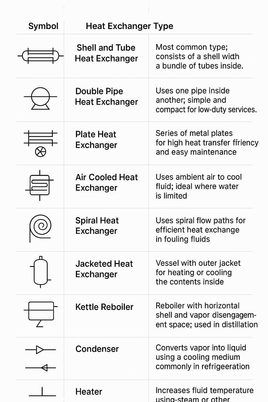
These symbols in p&id for heat exchanger diagrams show their importance. By knowing these symbols, engineers can understand a system’s design and function.
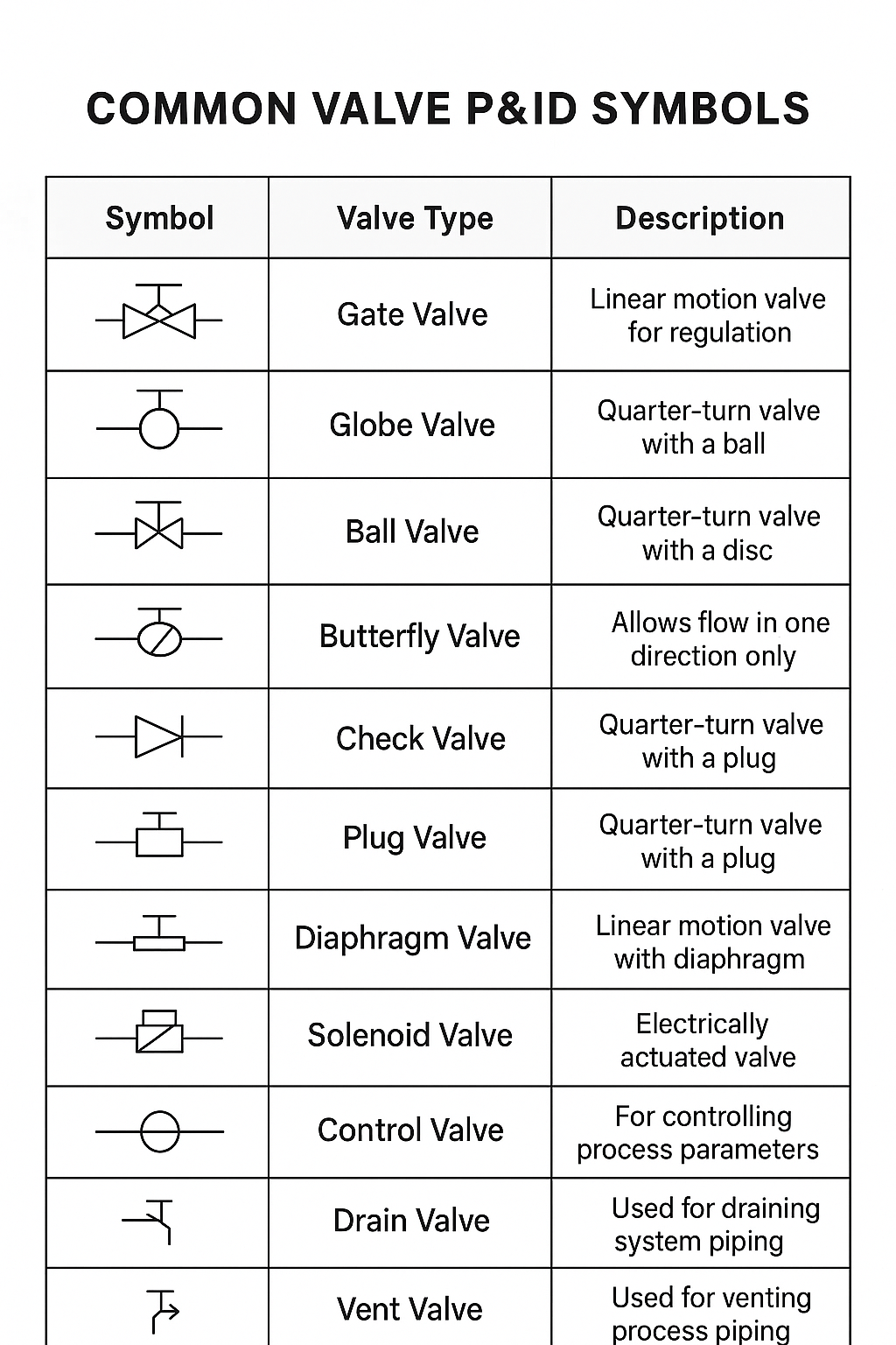
Valve P&ID Symbols:
In process engineering, P&ID (Piping and Instrumentation Diagram) symbols are key. They clearly show system parts, like valves. Valves manage the flow of fluids, stopping, starting, or controlling the flow of liquids or gases.
On a P&ID, each valve has its own symbol. This symbol tells you its type and what it does. These symbols are important for:
- Understanding how the system works
- Knowing where control is applied
- Identifying the valve type and its purpose
Getting valve symbols right is vital. It keeps the process safe, efficient, and easy to fix in any plant.
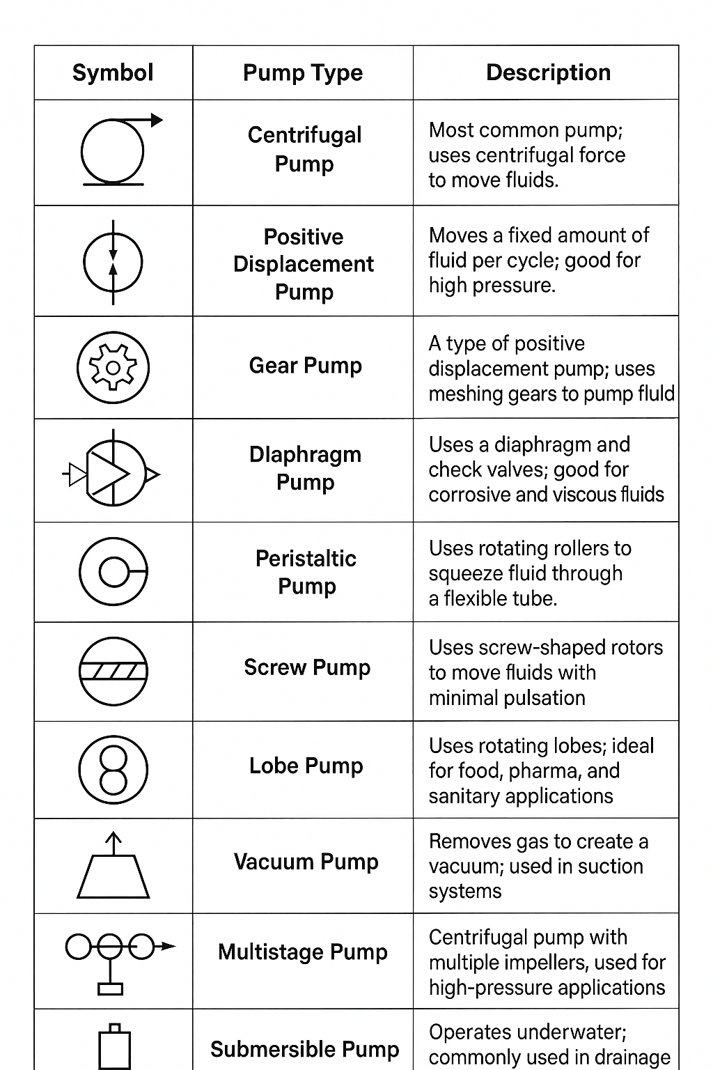
Pump P&ID Symbol:
In Piping and Instrumentation Diagrams (P&IDs), pumps are key parts. They show how fluids move in a system. Each pump has its own symbol to help identify its type, operation method, and application.
These symbols are the same everywhere to:
- Make sure communication is clear among all teams.
- Help with design, operation, and maintenance tasks.
- Show flow direction, drivers (like motors), and special features like seal systems or coupling types.
Knowing pump symbols is key for making and reading P&IDs. This is important in fields like oil & gas, water treatment, chemical processing, and power generation.
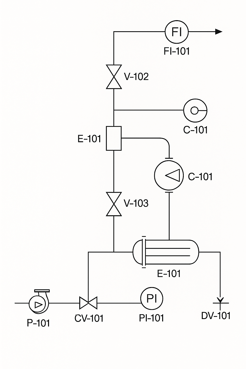
Example Of P&ID Drawing:
The P&ID (Piping and Instrumentation Diagram) shows the layout of a process system. It includes piping, equipment, valves, and instrumentation. This diagram is key for understanding the system’s flow paths and control logic.
It’s vital for design, operation, safety analysis, troubleshooting, and maintenance planning. This makes it a critical tool for anyone working with the system.
Applications of P&ID in Various Industries:
Piping and Instrumentation Diagrams (P&IDs) are key in many fields. They are used in oil and gas, pharmaceuticals, and water treatment. Each field has its own needs that P&ID diagrams meet well, making processes run better and more efficiently.
In the oil and gas sector, P&IDs help map out systems with pipelines, valves, and control tools. They give vital info for safety, upkeep, and better operation. In pharmaceuticals, P&IDs are vital for showing how products are made. They help follow strict rules and keep quality high.
Water treatment plants also rely on P&IDs to show how water is treated and to make sure equipment works right. Seeing how P&ID is used in different areas shows its flexibility and value in making operations successful.
Conclusion:
In this article, we’ve looked into the world of P&ID symbols. We’ve covered their roles in engineering and design. We’ve talked about different parts, like valve and pump symbols, and their importance in various industries.
Understanding these symbols is key for success in engineering. It’s not just helpful; it’s necessary.
My thoughts on P&ID end with a reminder. Learning to read these diagrams is an ongoing process. As technology changes, keeping up with new P&ID practices is important.
This knowledge improves your skills and helps create better, safer designs.
Lastly, I suggest diving deeper into P&ID symbols and their uses. This knowledge will help you handle complex projects better. It ensures your work is clear and precise.
FAQ:
What does P&ID mean?
P&ID stands for Piping and Instrumentation Diagram. It shows how different parts of a system work together. This is key for designing and documenting processes.
How do I read a P&ID diagram?
Start by learning the symbols for equipment, valves, and instruments. Look for arrows to see how things flow. This helps you understand the system’s operation.
What are P&ID drawings used for?
P&ID drawings show the physical and functional parts of systems. They act as blueprints for engineers. They help with installation, maintenance, and fixing problems.
What is the difference between a PFD and a P&ID?
A PFD gives a big picture of the process. It shows main parts and how they flow. A P&ID, on the other hand, goes into detail. It shows how instruments and controls work.
What are P&ID valve symbols?
Valve symbols in P&ID diagrams show different types of valves. Each symbol tells you what the valve does and how it works. This is important for controlling flow.
How can I find examples of P&ID diagrams?
Look in engineering books, industry guides, and online. Tutorials and case studies of real projects are also good resources.
Why is P&ID important in process engineering?
P&ID is key because it makes systems safer. It helps follow rules, troubleshoot, and is a reference for projects and operations.
What symbols are commonly used in P&ID diagrams?
Symbols for pumps, compressors, valves, heat exchangers, and instruments are common. Each has its own symbol to show its role in the system.
How are heat exchangers represented in P&IDs?
Heat exchangers have specific symbols in P&IDs. These symbols show their type and role in the system. Knowing these symbols helps understand how they improve efficiency.
What resources are available for learning more about P&IDs?
Many resources exist, like books, online courses, webinars, and training from professional groups. They focus on understanding P&ID symbols and their use.
What visual challenges do beginners face when interpreting P&ID symbols?
Beginners find symbols complex and connections hard to follow. Getting used to symbols and practicing helps overcome these issues.
In which industries are P&IDs applied?
P&IDs are used in many fields like oil and gas, pharmaceuticals, water treatment, and food processing. They help map out processes and ensure they run smoothly.